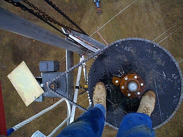
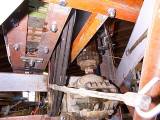
One other problem was the rotor, or more properly the top bearing.
I had used a 6000 pound "implement hub" designed for heavy agricultural loads in a stub
axle configuration. Even though it would be subject to large offset forces in my
application, I know it would have to carry such weights in it's normal usage.
Well, I was quite wrong again as it showed signs of leaning early on.
Here you can see Barry VA6DX standing on the sprocket that is bolted to the hub.
While nothing had failed to the point of being dangerous, it was time to do it
"more right" this time.
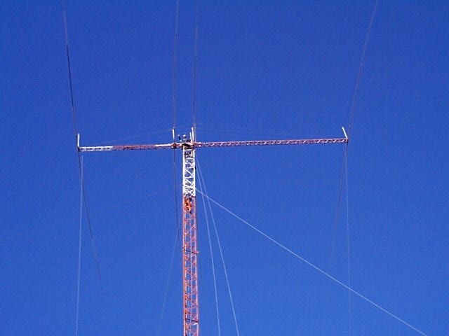
Getting the yagi in position at the start (1998) had been a
full 2 day job using a gin pole
and winch - taking it down that way would be not much less work and certainly not fun.
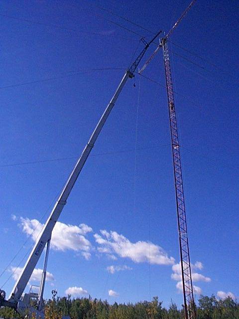 This shows the crane extended to 52.7 Meters (173 feet) and removing the
yagi.
(select image for larger view)
The next step was to remove the top tower section ( 6 meters, 20 feet )
and rework the rotor
system - much easier to do on the ground. A 3 meter (10 foot) section
would hold the new rotor,
making it easier to install with the crane.
This shows the crane extended to 52.7 Meters (173 feet) and removing the
yagi.
(select image for larger view)
The next step was to remove the top tower section ( 6 meters, 20 feet )
and rework the rotor
system - much easier to do on the ground. A 3 meter (10 foot) section
would hold the new rotor,
making it easier to install with the crane.
Strengthening the elements was fairly basic with 1 or 2 extra sizes of pipe inserted into the "weak" spots. Even though only the reflector was bent,
all elements were reinforced.
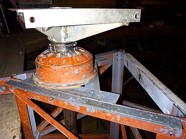
The mast was changed to a more conventional system
- a 10 cm (4") pipe with 1.2 Cm (.5 inch) wall supported by 2 bearings
and hubs (surplus jet aircraft wheels).

This rotor system was designed to slip in high winds, something not
possible with the usual worm drive and roller chain systems I usually use. The mast is connected to the output of a 25:1 gear reduction unit - not a worm gear. The input to this gear
is connected by a dual belt drive to a 60:1 worm drive. This will supply the breaking under normal winds but the intent was that the belts would slip in higher winds. The belt tension was made adjustable from the ground by hanging weights on a long rope
connected to an idler pulley. Fears that the belts would slip too easily are unfounded. I did remove one belt as the remaining one belt moderate tension is strong enough to shear off several 3/8 and 1/2 inch bolts holding the mast to the top of the gea
r drive. This happened as I was experimenting with the "right"
tension on the belts. This system has been replaced by the current worm
drive
Drive power is from a 500 rpm gearhead AC
1/2 horspower motor and so far, appears to have
adequate power to rotate under windy conditions.
Just over 2 minutes is required for a full rotation.
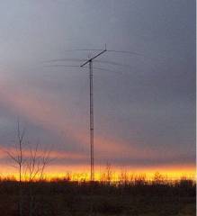
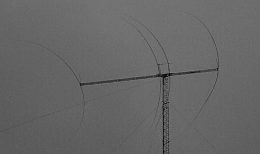
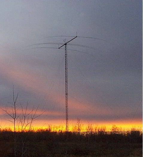
"80-Meters at sunset " Just looking West
80msunset-b.jpg
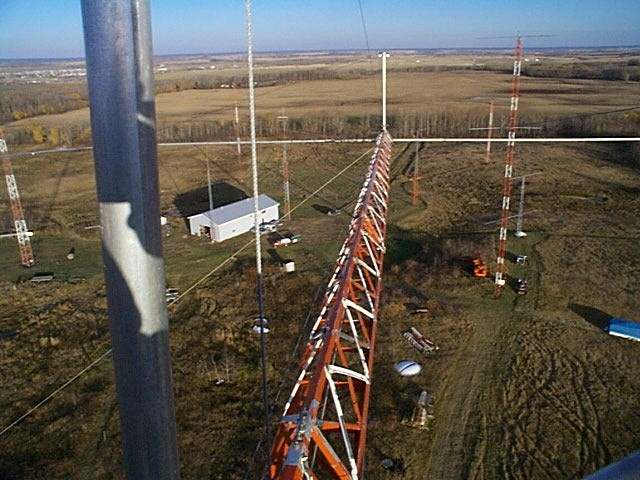
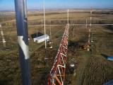 "DCP00558" Top of the tower, looking East.
The rotor system was reworked and reinstalled on Thursday,
September 28, 2000 at about 20:00 hr. UTC.